
CNC milling and CNC turning are the two most common CNC machining processes, but they produce fundamentally different geometries and require different machine tools. Milling uses a rotating cutting tool that removes material from a stationary workpiece mounted on a moving table, while turning rotates the workpiece against a stationary cutting tool. The choice between milling and turning is determined primarily by the part geometry—cylindrical parts are produced more efficiently on a lathe using turning operations, while prismatic parts with flat surfaces, pockets, and drilled holes are milled. Understanding the distinction is important because specifying the wrong process leads to unnecessarily high costs, longer lead times, or parts that cannot meet the required tolerances. Many parts require both milling and turning operations, and skilled manufacturing engineers design the part to minimize the number of machine transfers between operations.
The turning process is inherently faster than milling for cylindrical features because the material removal is continuous rather than interrupted. A CNC lathe can remove material at rates of 5 to 15 cubic inches per minute in aluminum, compared to 2 to 6 cubic inches per minute for a milling machine of equivalent spindle power. The surface finish produced by turning is also typically smoother, with Ra values of 0.2 to 0.8 micrometers achievable in a single pass compared to 0.8 to 1.6 micrometers for milling. The concentricity of turned features is inherent to the process because all diameters are machined in the same rotation, while milled features require precise fixturing to maintain positional accuracy between operations. For companies that require custom cnc turning for shafts, bushings, and threaded components, the lathe process delivers the best combination of speed, surface finish, and dimensional accuracy for cylindrical geometries.
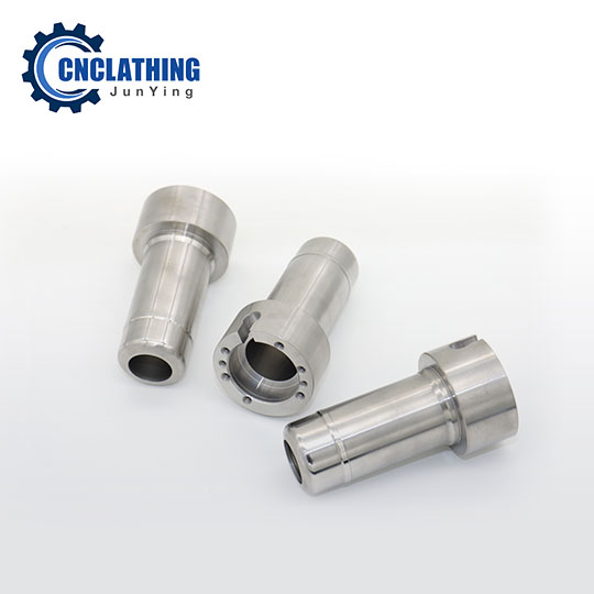
Five-axis milling machines and multi-tasking turn-mill centers blur the traditional distinction between milling and turning by combining both operations in a single machine. A turn-mill center has a rotating spindle that can operate in turning mode or indexing mode, along with a milling spindle and tool changer that can perform milling, drilling, and tapping operations without moving the part to a second machine. The advantage of multi-tasking machining is that complex parts requiring both cylindrical and prismatic features can be completed in a single setup, eliminating the positional errors that accumulate when transferring a part between machines. The cost premium for multi-tasking capability versus separate milling and turning machines is 30 to 60 percent for the machine tool investment, but the savings in setup time, reduced handling, and improved accuracy frequently justify the investment for production parts that require both process types.
The material removal mechanics differ significantly between milling and turning because the cutting action is continuous in turning and interrupted in milling. In turning, the cutting edge maintains constant contact with the workpiece, generating a continuous chip that requires a chip breaker to prevent long stringy chips from wrapping around the workpiece and tooling. In milling, each cutting edge enters and exits the material with every rotation, creating an interrupted cut that generates individual chips that fall away from the cutting zone. The interrupted cut in milling creates mechanical shock loading on the tool that requires tougher tool materials and geometries optimized for impact resistance, while turning tools can use harder, more wear-resistant grades that would chip under interrupted cutting conditions. The cnc machining parts designed for multi-tasking production benefit from design features such as standard thread sizes, consistent wall thicknesses, and generous internal corner radii that accommodate both milling and turning operations efficiently.
The selection between milling and turning extends to the fixturing and workholding approach. Milling fixtures must clamp the workpiece rigidly against cutting forces from multiple directions, typically using vises, toggle clamps, or custom fixtures with locating pins and datum surfaces. Turning fixtures must hold the workpiece concentric to the spindle axis, using chucks, collets, or faceplates that center the workpiece and transmit the cutting torque. The fixture design determines the maximum cutting forces that can be applied without workpiece movement, and poorly designed fixtures are the most common cause of out-of-tolerance parts. A turning operation using a three-jaw chuck can typically apply cutting forces of 500 to 2000 pounds of clamping force, while a milling operation using a precision vise can apply 1000 to 4000 pounds of clamping force depending on the jaw width and screw torque.
| Factor | CNC Milling | CNC Turning |
|---|---|---|
| Workpiece motion | Stationary or moving table | Rotating spindle |
| Tool motion | Rotating spindle + linear axes | Stationary tool + linear axes |
| Best geometry | Prismatic, flat surfaces | Cylindrical, concentric diameters |
| Surface finish typical | Ra 0.8 to 1.6 micro | Ra 0.2 to 0.8 micro |
| Material removal rate | 2-6 cu in/min | 5-15 cu in/min |
| Tool cost per part | Higher, multiple tools | Lower, fewer tools |
| Setup time | 30 min – 3 hrs | 10 min – 1 hr |
The cost impact of choosing the wrong process is significant. Milling a cylindrical part wastes material and machine time because the milling tool must traverse around the part contour rather than cutting the diameter directly. Turning a prismatic part on a lathe is difficult or impossible because the lathe cannot create flat surfaces and sharp internal corners efficiently. The rule of thumb for process selection is: if the part can be described by a diameter and a length, it should be turned; if it requires features on multiple faces with precise positional relationships, it should be milled. For parts that require both cylindrical and prismatic features, the design should group the cylindrical features so they can be turned in one chucking and the prismatic features so they can be milled in one setup, minimizing the number of part transfers between machines.